A 5 pole ignition switch is used to power the engine, accessories like headlight and taillight, and other electrical components with the battery on agricultural and construction machinery like tractors or forklifts. A 5 pole ignition switch wiring diagram helps the user of these vehicles to properly connect the particular wires to their designated connections to ensure proper function of the entire machine.
A 5 pole ignition switch wiring diagram helps the user to identify which wires go to which connection and enables them to properly connect and complete the electrical circuit in the vehicle to start and operate it. Following proper safety caution and guidelines, operators can utilize this diagram to wire all the connections perfectly in their vehicle.
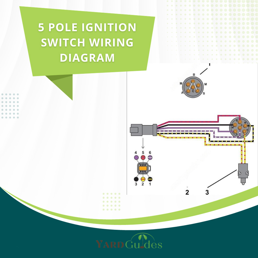
The 5 Pole Ignition Switch Wiring Diagram
A 5 pole ignition switch has 5 poles or terminals that take wiring connections. These 5 poles are usually labeled as B, S, I, R, and A. These poles are described in details below.
B terminal: B is called the battery terminal. Battery terminal is connected directly to the battery of your vehicle. This wire supplies constant power to the ignition switch. This point is connected directly to the positive terminal of your battery. All the parts of the vehicle such as the starter motor, the headlights, and so on take power from the battery through this switch when the switch is turned on. This terminal is also sometimes marked as BAT or BATT.
S terminal: S is used to mark the starting terminal. When the switch is turned, the battery supplies power through the B terminal into the S terminal and passes it to the starter motor which in turn starts to crank the engine and primes it for ignition. This terminal is sometimes marked as ST.
I terminal: I is marked to denote the Ignition terminal. This pole supplies power from the battery to the spark plug and the fuel pump to start the combustion cycle inside the engine to start and run the engine. This terminal is often marked as IGN.
R terminal: R is the accessories terminal. In some switches this is marked as ACC. This pole is connected to the accessories that are powered by the battery. This pole takes power from the battery and supplies it to accessories like headlight or radio to power them. Sometimes this terminal is named RUN as well.
A terminal: A terminal is used to connect other accessories that might be part of the vehicle. Sometimes other components that take electricity like the extra attached accessories like backhoe or soil tiller are connected to this pole. In some vehicles, this pole is connected with the ground, and in some cases, it remains disconnected with any other wires. Sometimes this terminal is marked as ACC.
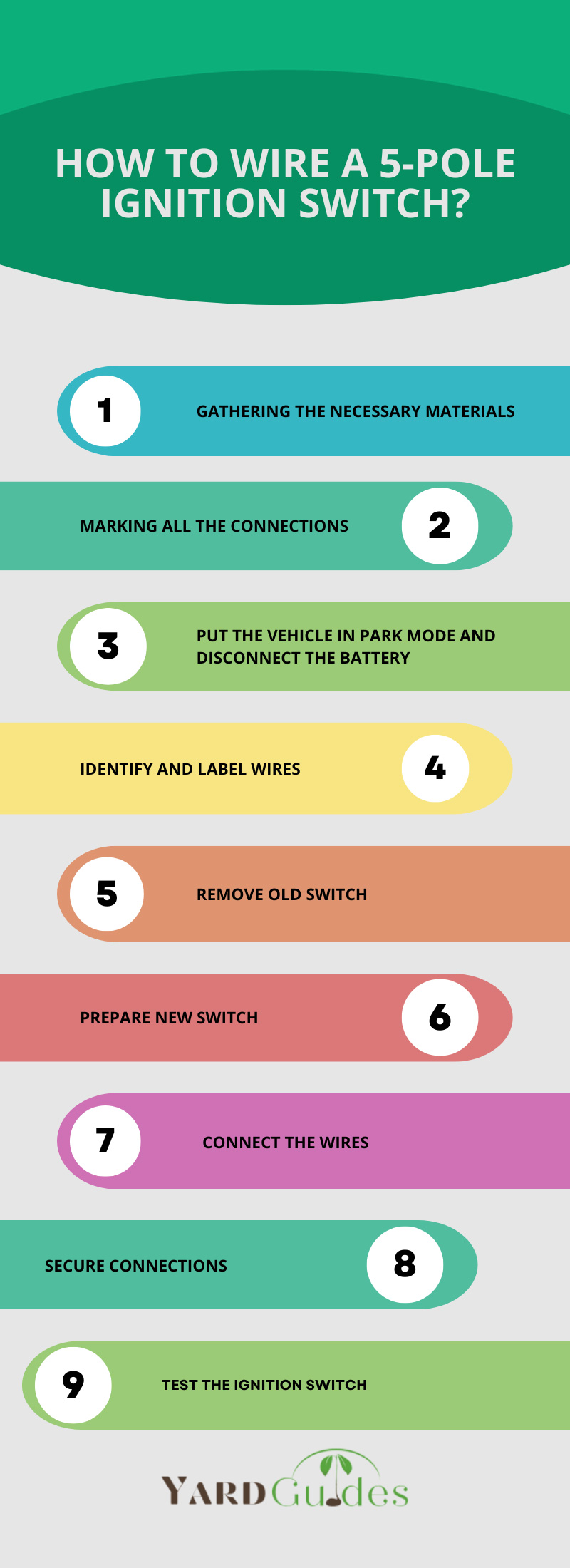
How to Wire a 5-Pole Ignition Switch?
Step by step guide to wire a 5 pole ignition switch is described below.
Step 1: Gathering the necessary materials
The basic things that you will require to wire the ignition switch to your vehicle are listed below.
- 5 Pole ignition switch
- Wire cutter
- Electrical tape
- Crimp connectors, Soldering iron (if necessary)
- Multimeter
- Protective gloves
Step 2: Marking all the connections
Second step is properly going through the whole diagram, the connections, and the wires that are going to be used in the connection. Trace all the connections to their source and make sure that all connections are working properly. Mark all the poles and which wires will be connected to them beforehand.
Step 3: Put the vehicle in park mode and disconnect the battery
Make sure that your vehicle is put in park mode and the engine is stopped fully before going any farther. Disconnect the negative terminal of the battery of your vehicle. Make sure that there is no connection to any other components that are taking power from the battery.
Step 4: Identify and label wires
Mark all the wires that are going to be connected with the poles. Familiarize yourself with the wires and use labels or markers if needed.
Step 5: Remove old switch
Carefully remove the old ignition switch if it remains installed on your vehicle. Disconnect the wires carefully to avoid damaging the connections.
Step 6: Prepare new switch
Identify all the terminals on your ignition switch. They are typically labeled as BAT, ACC, IGN, RUN, SIG1, SIG2, PWR, START and many more. These can mean different things depending on the switch model and manufacturer and they will be properly defined in the instruction manual of the switch. Read it thoroughly to understand the proper functions of every terminal.
Step 7: Connect the wires
Connect the BAT or B or the battery terminal with the battery. This usually does not have any fuse or anything between them. Directly connect this wire. Connect the accessories wire to the ACC or accessories terminal. Connect the ignition wire to the IGN/RUN terminal. Connect other terminals as described in the manual provided by the manufacturer.
Step 8: Secure connections
Use a crimp connector to secure the electrical connection between the wire and the terminal. Cover the connection with electrical tapes to provide proper insulation.
Step 9: Test the ignition switch
Connect the negative wire of your battery that you took off beforehand and twist the ignition key to check if everything is functioning properly. Vehicle will start if all the connections are established properly. Check the wires and connections again if the vehicle fails to start.
How Do You Check Ignition Wires?
Ignition wires can be checked with a multimeter.
How Do You Test an Ignition Wire With a Multimeter?
The steps of checking an ignition wire with a multimeter is given below:
Step 1: Set your multimeter to Ohms or continuity.
Step 2: Place the red probe on one wire ending and then place the black probe on the suspected ending.
Step 3: If the multimeter reads 0 or beeps, then that wire is conducting electricity properly.
Is the Ignition Switch Positive or Negative?
Ignition switch is positive.
What Is the Resistance of Ignition Wires?
The regular wires that are used in domestic vehicles are typically fiberglass core spark wires with 10,000-12,000 ohms of resistance per foot. This standardization is done by The Society of Automotive Engineers.
How Do I Know if My Ignition Wires Are Bad?
You will know that your ignition wires are bad if turning the ignition switch fails to start the vehicle. Check the wirings with a multimeter. Set the multimeter to continuity or ohm mode and touch one probe with one opening end and other probe to the suspected end. The wiring is functioning properly if the multimeter beeps or shows 0. Change the wire if it fails to show any digit which means that the wire is disconnected at some point due to corrosion or wear and tear.
What Color Are the Ignition Wires?
The color of the wires are given in the table below:
| Wire Color | Terminal |
| Red | 1 (power) |
| Black | 2 (ground) |
| Yellow | 3 (starter) |
| Green | 4 (ACC) |
| White | 5 (IGN) |
Can You Install a 5 Pole Ignition Switch?
Yes, anyone without prior in depth knowledge about electronics can easily install a 5 pole ignition switch in their vehicle by following the proper steps and by abiding the safety concerns.
Are There Any Safety Concerns When Working With Ignition Systems?
The biggest safety concern while changing or fixing the ignition switch is that the vehicle can accidentally start and supply electricity through the wires that may be in direct contact with you. This can result in accidental shocks and the vehicle accidentally moving. This can easily be mitigated by shutting the engine down completely, removing the negative connection from the battery, and putting the vehicle in park mode. Another safety concern is about avoiding accidental shocks. This can be obtained by using protective gloves while handling electrical wires.